The series resistance of the patch pipette (Rs) produces two undesired effects in whole-cell voltage clamp recordings:
i. Rs introduces a voltage error, causing the cell membrane voltage (Vm) to deviate from the desired clamping voltage whenever ionic current flows. This voltage error is often called an “IR” drop since it is given by Ohms law (V=IR), where I is the patch pipette current;
ii. Rs lowers the temporal resolution of the voltage clamp, often to the extent that rapid physiologic processes cannot be accurately measured. The temporal resolution is quantified by the access time constant τa = Rs*Cm , where Cm is the cell capacitance. (Note that increasing τa , either by increasing Rs and/or Cm, decreases the temporal resolution).
These two effects are collectively referred to here as “Rs errors”.
The Goal of Rs Compensation
The goal of Rs compensation is to reduce, and ideally eliminate, Rs errors from whole-cell voltage clamp recordings. Therefore, Rs compensation should reduce (and ideally eliminate) the Rs voltage error when to ionic current flows, and it should increase the temporal resolutions of the voltage clamp by reducing τa .
Standard Rs Compensation – The Usual Approach
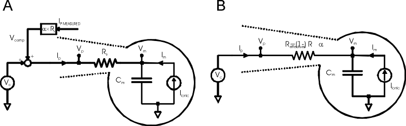
Fig.1: Standard Rs compensation
A. Voltage clamp of pipette and cell, with standard Rs compensation added as positive feedback. B. Equivalent circuit.
Vc = command voltage; Ip = pipette current; Vp = pipette voltage; Rs = pipette series resistance; Vm = cell membrane voltage; Cm = cell capacitance; Im = cell membrane ionic current; Ipmeasured = measured pipette current; α = Rs compensation scaling factor [0,1]; Reffective = effective series resistance.
Standard Rs compensation (Fig 1A) is the usual approach commercial patch clamps employ to address Rs errors. Referring to Fig 1A, a fraction of the pipette “IR” drop is continuously computed (Ipmeasured*Rs*α) and is then added to the voltage clamp command as a correction signal, forming a positive feedback loop. The result of standard Rs compensation is summarized in the equivalent circuit of Fig 1B, which shows that the positive feedback loop acts to reduce the effective value of Rs by the factor (1-α). For example, if α is set to 0.8 (80% Rs compensation), Reffective = (1-0.8)*Rs =0.2*Rs (20% of the original value Rs). Therefore, 80% Rs compensation reduces Rs voltage errors by 80% and simultaneously increases the temporal resolution by the same amount (τeffective=Reffective*Cm).
Standard Rs Compensation Hits the 'Speed Wall'
Fig 1B predicts that Standard Rs compensation should completely eliminate Rs errors when α is set to 1 (i.e. the full IR drop across the electrode is used as positive feedback) since the effective Rs is then predicted to be equal to 0. In practice standard Rs compensation can’t do this because the entire positive feedback loop becomes unstable when alpha is increased beyond ~ 0.9 (90% Rs compensation).
This effect is shown graphically in Fig 2, which plots membrane voltage in response to ionic current steps with increasing amounts of Rs compensation.
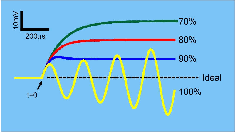
Fig.2: Voltage Error with Standard Rs Compensation
Rs voltage error (Vm - Vhold) in response to repetitive 10nA ionic current steps (applied at t=0) with increasing amounts of standard Rs compensation.
Circuit as in Fig 1A. Iionic = 10nA step applied at t=0; Rs = 10Meg; Cm = 50pF; Vhold = constant; bandwidth of Ipmeasured = 50kHz;
As Rs compensation is increased, the Rs voltage error is reduced and the voltage clamp speed is increased, but beyond 90% Rs compensation the circuit produces unbounded oscillations which would kill the cell (yellow trace). Because of this, it is impossible for standard Rs compensation to fully eliminate the IR drop across the patch pipette.
A clue as to why this occurs is to note that standard Rs compensation tries to reduce the effective access time constant (τeffective ) to 0 as Rs compensation approaches 100%. This is equivalent to creating a voltage clamp that responds instantaneously. Instantaneous response (or infinite bandwidth) is of course not possible for any physical system. A full numerical analysis (see, for example, the appendix in Sherman, et al) shows that stable Rs compensation requires the bandwidth of Ipmeasured (used to create the feeback signal) to be at least five times the compensated voltage clamp bandwidth. Since the bandwidth of Ipmeasured is limited by the electronics, the voltage clamp speed attainable with standard Rs compensation is limited as well, as is the maximum percentage Rs compensation. Therefore, standard Rs compensation always leaves a residual, finite Rs voltage error in whenever ionic current flows.
The Alembic Rs Compensator™ Eliminates the 'Speed Wall'
The great utility of the Rs Compensator™ is that it eliminates the “speed wall” described above which limits standard Rs compensation.
Fig.3 illustrates improvement:
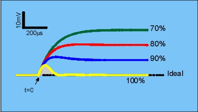
Fig.3: Voltage error with the Rs Compensator™.
Rs voltage error using the Rs Compensator™. All other parameters as described in Fig 2.
Comparing Figs 2 and 3 reveal similar performance below 90% Rs compensation. However, the Rs Compensator™ allows 100% Rs compensation to be achieved whereas standard Rs compensation oscillates. At 100% Rs compensation (yellow trace, Fig 3), there is a transient Rs voltage error for ~ 200us (grayed “error zone”) after which the Rs voltage is error eliminated, as shown by the trace returning to the ideal “baseline” level. Significantly, the Rs Compensator™ eliminates voltage error regardless of the magnitude of the ionic current flowing through the patch pipette.
What’s going on?
Standard Rs compensation oscillates because the voltage clamp bandwidth increases without limit as Rs compensation approaches 100%. In contrast, the Rs Compensator™ limits the voltage clamp bandwidth at 100% Rs compensation, thereby avoiding the stability constraint (See the Theory section of US patent 4,700,427 for a mathematical derivation of the Rs Compensator™). In practice, the Rs Compensator™ allows the voltage clamp bandwidth to be selected, such that higher bandwidths result in faster elimination of the Rs voltage error (i.e. the amplitude and duration of the gray “error zone” in Fig 3 is reduced). Going to the extreme of trying to eliminate the “error zone” altogether brings about the same instability associated with standard Rs compensation. In other words, in the limit of very high voltage clamp bandwidths, standard Rs compensation and the Rs compensator are equivalent.
THE Rs COMPENSATOR™ BENEFITS:
+EASE OF USE The wide stability of the Rs Compensator™ makes it very easy to use and tune in comparison to standard Rs compensation. Even at full Rs compensation, the Rs Compensator™ remains stable as pipette conditions shift during an experiment (fluid level, whole-cell access resistance, etc). In contrast, small changes in pipette capacitance or series resistance very quickly cause standard Rs compensation to oscillate and kill the cell.
+ VOLTAGE CLAMP CONTROL LARGE, FAST CURRENTS The Rs Compensator™ makes it much easier to voltage clamp large, regenerative currents, such as INa, under physiologic conditions. When clamping regenerative currents such as INa, Rs voltage errors of only 1-2 mV will trigger a cellular action potential with complete loss of the voltage clamp. Since standard Rs compensation, even pushed to its limit, nearly always leaves a voltage error greater than this threshold, other means must be used to further reduce this voltage error so as to maintain voltage control. Routine methods employed, such as lowering Na+ gradients or cooling the entire preparation, introduce non-physiologic conditions that can compromise the validity of the experiment. Even then, it is still extremely difficult to maintain voltage control in excitable cells. In contrast, the Rs CompensatorTM eliminates Rs errors in < 200us, independent of the magnitude of the ionic current. It is therefore possible to voltage clamp very large Na+ current under physiologic temperatures concentration gradients while maintaining voltage control.
Alembic Instruments Inc. 3285 Cavendish Blvd. Suite 570 Montreal, Qc, H4B 2L9 Canada
Phone: 514.678.7924 Fax: 866.240. 2738